


Vehicle Applications
GMC Sierra
- (2022-UP) | 1500 Crew Cab
- (2024-UP) | 2500HD and 3500HD Crew Cab

→ Installation Time

Audio Package Installation Instructions
With Factory BOSE Amplified System
Introduction
The following installation instructions will guide you through the installation process:
- Replace the Front Dash, Front Door, and Rear Door Speakers in the factory locations.
- Add Amplifiers and a Subwoofer.
TIP Before you begin, review these instructions thoroughly and ensure that all parts are present and tools are available.
WARNING Metra Electronics does not assume any responsibility for damage resulting from incorrect installation.
↳ Parts List
Number | Component | Quantity |
1 | VIBE 6.5” Rear Door Speakers (Pair) | 1 |
2 | VIBE 2.7” Dash Speakers (Pair) | 1 |
3 | VIBE 6x9” Front Door Speakers (Pair) | 1 |
4 | 100 x 4 D Class Amplifier (4 Channel Amplifier) | 2 |
5 | VIBE Shallow 10” Subwoofer | 1 |
6 | Ported Subwoofer Enclosure | 1 |
7 | Rear Door Speaker Adapter Plate (82-3006) (Pair) | 1 |
8 | Front Door Speaker Adapter Plate (82-3006) (Pair) | 1 |
9 | Speaker Harness (72-4572) (Pair) | 2 |
10 | Tweeter Speaker Harness (72-4573) (Pair) | 1 |
11 | 6” Speaker Baffle Kit (Pair) | 1 |
12 | 4GA Amp Kit with fuse holder and distribution block | 1 |
13 | Vehicle-Specific Amp Panel | 1 |
14 | ETH1-DSP Interface and Harnessing | 1 |
↳ Required Tools
- Drill
- Philips Driver
- Flat Blade Driver
- Hook / Pick Tool
- Panel Tool
- Ratchet
- Sockets: 7mm, 10mm, 13mm
- Torx: T20, T50
- Wire Cutter/Crimper Tool
Before You Begin
WARNING Using a 10mm socket, disconnect the Negative battery post from the vehicle battery (circled below).

Dash Speaker Removal
Follow the steps below the remove the speakers from your dashboard.
- Open the upper and lower handle covers (1) with a small flat-bladed tool to access and remove the two (2) 10mm bolts.

- Pull the top of the panel toward the inside of the vehicle to disengage the upper panel clip.
- Once the clip is released, pull the panel back toward the front seat and slowly rock it back and forth.

- Using a plastic pry tool, release the panel clips along the front edge of the dashboard panel.

- (Optional) If equipped:
- Disconnect the electrical connector for the heads-up display (circled below).

- Remove two (2) 7mm screws securing the dash speaker (highlighted below).
NOTE Metra recommends using a SKU-Driver.

- Disconnect the electrical connector (circled below).

- Repeat the above steps to remove the speaker from the opposite side of the dash.
Dash Speaker Installation
Follow the steps below to install the speakers in your dashboard.
The 2.7” speakers include a set of aluminum rings that will attach to the speaker and provide mounting points to secure the speaker into the dash. To install the ring onto the speaker:
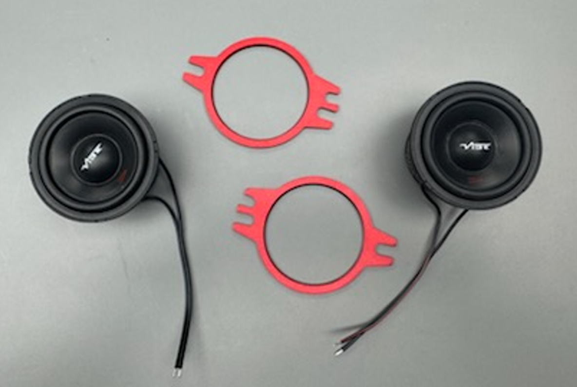
- Place the speaker face down on the workbench.
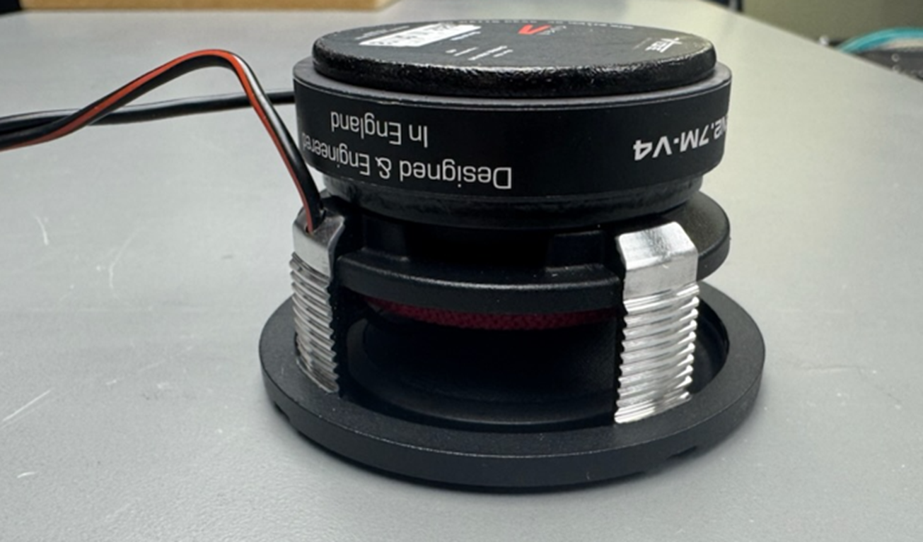
- Place the ring onto the speaker.
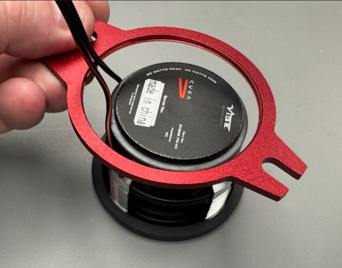
- Slowly turn the ring counter-clockwise to line up the threads.
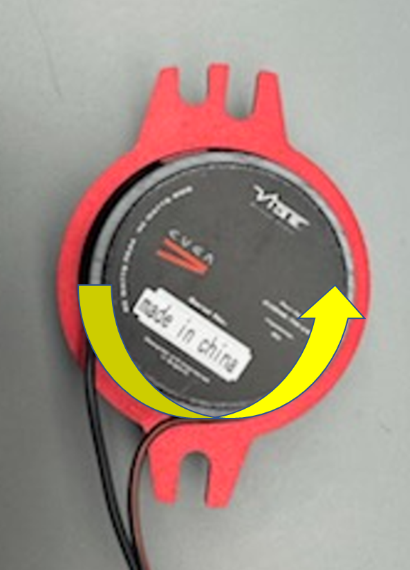
- Once the threads have lined up, slowly start to turn the ring clockwise to tighten onto the speaker.
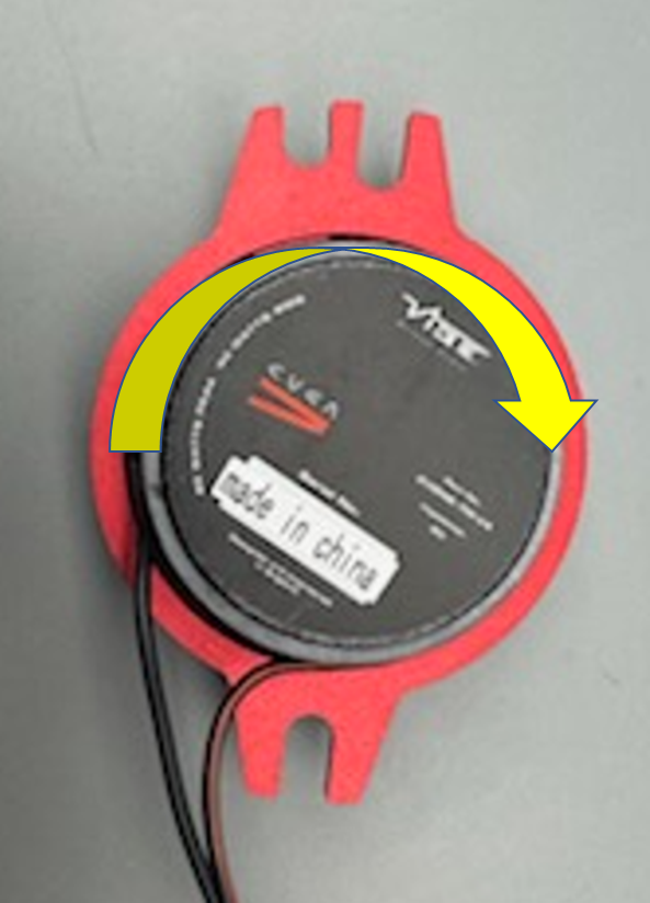
TIP Ensure that you do not cross thread the ring on the speaker.
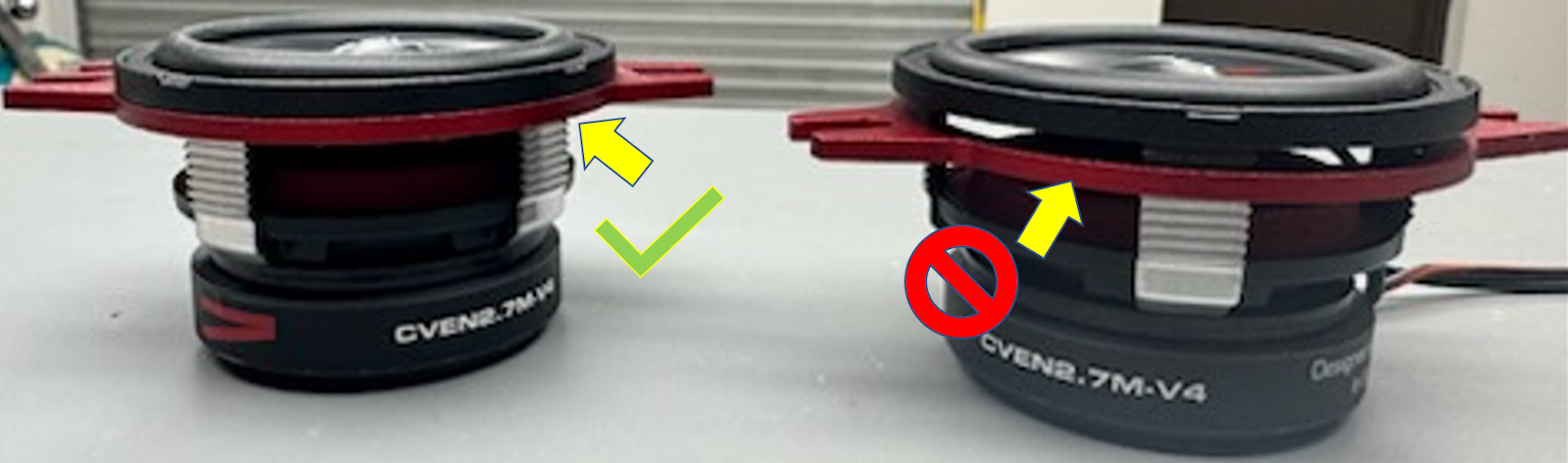
- Continue turning the ring until it is seated against the speaker.
- Using the 72-4573 speaker harness and the supplied butt connectors, crimp the harness wire to the speaker wires.
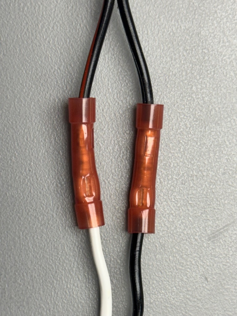
- Connect the White wire from the 72-4573 to the Black/Red wire from the VIBE 2.7” speaker.
- Connect the Black wire from the 72-4573 to the Black wire from the VIBE 2.7” speaker.

- Install the 82-3024 into the OE speakers’ location:
- Plug the 72-4573 Speaker Harness into the OE speaker connector.
- Install the VIBE 2.7” speaker into the opening, securing it with the (2) 7mm screws.
- Reassemble the vehicle dash in reverse order (show below).


Door Panel Removal
Follow the steps below to remove your door panels.
- Use a small pick tool or a flat-blade screwdriver to remove the cover inside the door handle.
- Remove the two (2) 7mm bolts behind the cover.
- Using a 7mm socket, remove the two (2) bolts at the bottom of the door trim that secures the panel to the door (circled).


↳ Remove the Front Side Door Trim
Using a pry tool, follow the steps below to remove the front side door trim:
- Start at the front lower corner and pull the trim away from the sheet metal to disengage the panel clips.

- Move to the rear lower corner and repeat the process to unsnap the panel clips.

- Proceed to the rear center of the panel and pull the trim to release the panel clips.

- Proceed to the front center of the panel and pull the trim to disengage the panel clips.
- Unhook the trim from the window’s edge by pulling it upward using both hands.

- Remove the lock knob and rod.
WARNING Ensure that the lock rod remains in the locking rod clip to prevent damage to the latch should it pivot.
- Disconnect the door lock retainer cable from the front side door trim and the inside handle.

- Disconnect the electrical connector (circled below).

- Remove the door panel and place it on a clean, flat surface.
- Repeat the above steps to remove the speaker from the opposite side of the vehicle.
Front Door Speaker Installation
Follow the steps below to install your front door speakers.
- With the door panel removed and the speaker exposed, remove the one (1) 7mm screw at the top of the speaker bracket.

- With the screw removed, lightly pull on the speaker so it separates from the door panel, and then pull UP to remove the speaker from the door.
- Disconnect the speaker harness.

- Locate one of the 82-3004, 72-4572, and the VIBE 6x9 Speakers.

- Before installing the speaker into the speaker adapter, attach the speaker harness adapter onto the speaker.
- Cut the terminals off the harness and strip back the wire to allow securing to the screw-down terminals of the 6x9 speaker.

- Install the speaker into the speaker adapter.

- Attach the speaker harness to the factory harness located in the door.

- Install the speaker into the door and secure it with the (1) 7mm screw you removed.

NOTE We have included (2) self-tapping screws better to secure the speaker adapter plate to the door. The speaker adapter has (2) holes already pre-drilled to allow for this installation.

- Reassemble the door in reverse order.
- Repeat the process to install the speaker on the other side of the vehicle.
Rear Side Door Trim Removal (Crew Cab)
Follow the steps below to remove your rear side door trim (crew cab).
- Remove the rear side door pull cup liner.

- Unscrew the (2) 7mm bolts securing the rear side door armrest pull cup.
- Remove (1) 7mm bolt at the bottom of the door panel.

- Starting at the rear bottom corner, use a plastic pry tool to pull the rear side door carefully and trim away from the door.
- Release the panel clips around the perimeter.
- Detach the door lock retainer cable from the door trim and inside handle.


- Disconnect the electrical connector.

- Remove the rear side door trim and place it on a clean, flat surface.
- Remove one (1) 7mm screw at the top of the speaker bracket.

- With the screw removed, lightly pull on the speaker so it separates from the door panel.
- Pull up to remove the speaker from the door.
- Disconnect the speaker harness.

- Prep the 82-3006 speaker adapter plate by removing the excess tabs with pliers.

- Locate one of the 72-4572, IBSBF65 and the VIBE 6.5" Speaker.

- Connect the 72-4572 speaker harness to the speaker.
- Install the speaker baffle into the speaker adapter
- Install the speaker.

- Remove the paper and place it inside the door panel, directly behind the speaker, to install the sound baffle.

- Install the VIBE 6.5" into the opening, securing it with the provided screws.
- Reassemble the door in reverse order.
- Repeat the process to install the speaker on the other side of the vehicle.

Amplifier Wiring Routing
The amplifier kit includes a 4GA Red power wire that will run from the vehicle's battery to the cab's rear. It also includes the MANL fuse holder with a 100-amp MANL fuse.
Follow the steps below to properly route your amplifier wiring.
- Open the hood and remove the cover on top of the battery.
TIP In this vehicle, the battery is located against the passenger firewall.

- The amp kit comes with a short piece of 4GA wire marked in the image that connects to the vehicle battery terminal.
TIP Because the vehicle ground wire was disconnected in Step 1 above, the short Red power wire can be connected to the battery and then to the T-Spec fuse holder.

- Using a 13mm socket, remove one of the available lugs off the positive side of the battery to allow the installation of the ring terminal of the 4GA power wire.

- Insert the 100amp MANL fuse into the holder using a T-20.

- Connect the longer piece of 4GA power wire to the fuse holder.

- Secure the 4GA power wire and fuse holder using the provided zip ties.

- The 4GA runs down the back of the firewall to the vehicle frame rail.
WARNING Avoid areas with high heat exposure.

- Run the power wire along the frame and zip tie along the main harness toward the back of the vehicle.
TIP You will come to a silver plug. In a subsequent step, you will drill for the grommet here.

Trim and Panel Removal
Follow the steps below to remove your trim your seat track panels.
- Use a suitable plastic trim tool to gently pry upwards and release the panel clips.
- Remove the front seat adjuster track finish cover.

- Beginning at the rear of the front side-door sill-garnish-molding, pull upward at the B-pillar joint to release the Up/Down clips.

- After releasing the clips, rotate the molding inward, then pull it rearward to disengage the two clips on the forward vertical wall (arrow blow).

NOTE The kick panel and door sill are two pieces of plastic welded to make a single piece. Do not attempt to separate the joint closer to the kick panel. The single will come out after you have removed the clips.

- Use a flat-bladed plastic tool to disengage the panel clips between the rear side door sill garnish molding and the center pillar lower trim panel.

- Pull upward from both sides of the rear-side door-sill garnish-molding to release the panel clips from front to rear.
- Remove the molding.

- Remove the anchor plate cover to expose the front seat belt anchor plate tensioner bolt.

- Using a plastic pry tool, separate the upper and the lower B-pillar panels.
- Separate the panel from the B-pillar.

- The above step will expose a grounding point used for the amplifier grounds in a later step (circled below).

Rear Seat Removal
Follow the steps below to remove your rear seats.
- Remove the headrests from the back seat.

- In front of each headrest guide, depress the edge of the seat cushion to expose the headrest guide release.
- Using a flat tool, push the tab inward and pull the guide upward to remove it from the seat frame.

- Do this for all headrest guides.
- Lift and fold the rear seat cushions into the upright position.
- Using a T-50 Torx, unscrew the bolt holding the retractor in place and disconnect the electrical connector.
- Move the seat belt anchor plate and buckle out of the way.


- Remove the (4) 10mm bolts securing the seat back frame.

- Lower the rear seat cushions back into place, guide the seat belt anchor plate, and buckle through the opening.
- Using a hook tool, locate the three latches securing the rear seat back by locating the indentations on the back edge.
TIP This will take some time. Be patient.

- Pull the latches upward to release them.
- Lift the seat back cushion out of the vehicle.

Removal of Bose Amplifier & Power Inverter
Follow the steps below to remove your Bose amplifier and power inverter (highlighted below).

- Disconnect all electrical connectors.

- Remove the three (3) 10mm nuts that secure the Bose amplifier to the back wall and remove the amp.
NOTE The Bose amplifier will no longer be used in the vehicle.

- Remove the three (3) 10mm nuts that secure the power inverter to the back wall.

- Unclip the wiring harness mounts.
NOTE The AC/DC inverter will be relocated later in the installation.

Audio Equipment Installation
This kit includes a precut board and a set of determined mounting locations for the equipment. This board mounts all the audio equipment, including the Bose interface. It is designed to use the existing studs and nuts on the truck's back wall. This board also has a predetermined location for the inverter removed in the previous section.
Follow the steps below to install your audio equipment.
TIP The installation of the product onto the board can be completed outside the vehicle.

- Using the supplied screws, mount the amplifiers in place.
TIP RCAs should point up.

- Using the provided hook-and-loop pad, secure the ETH1 DSP in place.
TIP The connectors should be pointing up.

- Using the supplied screws (smaller heads), mount the distribution block. The Vibe amplifiers are fused inside the amplifier case for added protection against short circuits.

TIP The Power inverter will be mounted to the board after the installation step.
- With the amps and distribution block mounted, you will have two remaining screws; they will be used to mount the inverter.

NOTE The final step of this process differs depending on the presence of seat-back storage compartments. Review the options in Step 5 carefully.
- If your seat-backs:
- Open to the storage compartments: Remove the foam from the back seat. Mount the inverter to the amp board without any additional modification.
- Do not have storage compartments built in: Cut the foam on the back seat before reinstalling or relocating the inverter elsewhere. This will be handled during a later step of the installation and reassembly.
WARNING Before reassembling the back seat, test the system to ensure all steps have been successful.
Wiring the Board
- Connect the 16-pin connector into the ETH1 DSP and plug the RCAs into Amp1 and Amp2.

- Using the provided 8GA Red power wire, connect to the distribution block and to the respective amplifiers.
- Distribution Block Screw T-20 Torx
- Vibe Amplifier Screw 5/32 Allen
NOTE These wire runs are long. They will be grounded to the bolt on the passenger side of the B-pillar.

- The kits come with two different OE connectors that plug into the 8-pin connector on the ETH1 DSP.
- LD-VB-ETH1 harness is for the year ranges 2019-2021.
- LD-VB-ETH2 harness is for the year ranges 2022-2024.
- Off each of these harnesses is an Orange and Black wire marked Bass Knob.


TIP To have control over the subwoofer volume, the bass knob will need to be run to a location accessible to you. See Bass Knob Installation.


- The LD-VB-ETHSPH will connect to the OE plugs removed from the factory Bose amplifier.
TIP The harness uses the vehicle's OE speaker wiring, so no additional wiring will need to be run.
- On both the LD-VB-ETH1 and LD-VB-ETH2, there is a 2-pin Molex connector with Yellow and Black wires. That 2-pin plug is connected to the mating connector on the LD-VB-ETHSPH harness.

- When wiring the speakers using the LD-VB-ETHSPH, speaker wires are marked for which amp and the channel they need to be connected to on that amplifier. You will also have the Remote Wire to connect in this harness

Bass Knob Installation
NOTE If you would like to custom tailor your bass response, the Axxess DSP that comes pre-tuned with your Vibe Audio Kit has been tuned on an RTA by a professional audio engineer.
WARNING Metra Electronics does not recommend changing any of the DSP settings.
To gain more bass response, you can choose between the two options below.
↳ Bass Knob Installation: Option 1
- In the OE radio, access the EQ Settings and add or remove any of the BASS, MIDRANGE or TREBLE levels.
- Adjusting the factory EQ will have an effect on the overall sound of the vehicle and will not remove the tune that comes pre-loaded on the DSP.
- With the radio on, find the SETTINGS icon (Fig A).

- Choose AUDIO SETTINGS, and then EQUALIZER (Fig B).

- Adjust the BASS, MIDRANGE or TREBLE settings to your preference (Fig C).

↳ Bass Knob Installation: Option 2
The Axxess DSP that comes in your Vibe Audio Kit does come with a BASS KNOB (Fig D).

To Install the Bass Knob and have extra control of the subwoofer:
- Connect the knob to the matching wires on the DSP harness (Fig E).


- Make the connections with the supplied butt connectors.
NOTE The wire length on the bass knob will not be long enough to make the knob reach the front dash. You can use standard speaker wire (not included) to lengthen the wires to allow mounting the bass knob in front seat of the truck.
- Once the knob is connected and installed with the included hardware, you can program the knob using the following steps carefully:
- With the radio volume lowered, first:
- Turn the knob ALL THE WAY DOWN.
- Turn the knob ALL THE WAY UP.
- Perform the sequence alternately 5 times within 10 seconds.

- A series of chimes will sound from the front left dash speaker to confirm programming.
NOTE After programming the knob, you may notice that the level cuts off as you turn the knob all the way down. This feature allows the subwoofer to be muted. If you add a 5.6k ohm resistor in series on the ORANGE wire of the bass knob you will have full range of the knob.
WARNING Metra Electronics recommends implementing only one of the options above. Implementing both options could negatively affect the audio quality of the subwoofer and possibly damage the system.
↳↳ Amp 1 Speaker Wiring
Follow the wiring instructions in the table below and use the Amp 1 graphic to match.
Amp Channel | Speaker | Wire Color |
CH1 + | LF Tweeter + | Yellow |
CH1 - | LF Tweeter - | Yellow / Black |
CH2 + | RF Tweeter + | Brown |
CH2 - | RF Tweeter - | Brown / Black |
CH3 + | LF Door + | White |
CH3 - | LF Door - | White / Black |
CH4 + | RF Door + | Gray |
CH4 - | RF Door - | Gray / Black |

↳↳ Amp 2 Speaker Wiring
Follow the wiring instructions in the table below and use the Amp 2 graphic to match.
Amp Channel | Speaker | Wire Color |
CH1 + | LR Door + | Green |
CH1 - | LR Door - | Green / Black |
CH2 + | RR Door + | Purple |
CH2 - | RR Door - | Purple / Black |
CH3 + | Subwoofer + | Red |
CH3 - | NA | - |
CH4 + | NA | - |
CH4 - | Subwoofer - | Black |

Amplifier Settings
After wiring the amps, you can set the levels before installing the amp board into the vehicle. Use a small flat-blade screwdriver to make the adjustments.
↳ Amp 1 Settings
Setting | Adjustment |
X-OVER | FR (FULL RANGE) |
HPF | Turn COUNTER CLOCKWISE until it stops |
LPF | Turn COUNTER CLOCKWISE until it stops |
GAIN | Turn CLOCKWISE to the 11 o’clock position |
INPUT MODE | Button should be OUT for 4-Channel Input |

↳ Amp 2 Settings
Setting | Adjustment |
X-OVER | FR (FULL RANGE) |
HPF | Turn COUNTER CLOCKWISE until it stops |
LPF | Turn COUNTER CLOCKWISE until it stops |
GAIN | Turn CLOCKWISE to the 11 o’clock position |
INPUT MODE | Button should be OUT for 4-Channel Input |

Mounting the Completed Amp Board
- Bring the amp board to the vehicle, line up the OE studs, and slide the board into place.
- Secure the board using the (3) OE 10mm nuts.


- Plug in the OE connectors.


- Using the supplied zip-ties, secure all wiring into bundles that will not interfere with the seat back mounting locations.
Wire Connections
- Remove the jack from under the rear passenger seat to allow easier access to the floor for drilling the grommet location for the power wire.
- Remove the wing nut and turn the RED knob on the jack to lower the piston and remove from the mount. There are (2) 10mm nuts that need to be removed to move the jack mount.

- Pull the carpet back to expose the metal cab floor.

- Locate the round plate found under the cab while running the power wire.

- Using a Unibit, drill a hole to accommodate the 1" rubber grommet included in the kit.
- Cut the grommet to allow the 4GA power wire to pass through.
- Feed the power wire from under the vehicle into the cab of the vehicle through the grommet and toward the amp rack to connect to the distribution block.
- Connect the 4GA power to the distribution block using a T-20 Torx.
- Remove any excess length.


- Remove (4) 7mm screws from the wire channel running along the rear door. This will provide a clear location to run the ground wires without interfering with any of the panels during reassembly.

- Run the ground wires down the vehicle's passenger side and connect to the ground lug in the B-pillar using a 10mm ratchet.

- Using the included zip ties for wire management, prepare the area for reassembly.
TIP Ensure that none of the new wiring will interfere with the installation of the back seat.
Final Steps
This kit includes a DSP tune specifically for this vehicle and the equipment. No additional programming or setup is required. Simply plug in and wire the equipment to complete the installation.
WARNING To avoid potential damage, you must properly connect your speaker wires to the correct channels for the VIBE amplifier. Damage caused by improper connection will not be covered under warranty.
After connecting the speaker wires to the amplifier, the speaker wires must be connected to the terminal of the subwoofer.
- Run the subwoofer speaker from the amp to under the driver side rear seat.

- Place the enclosure under the seat and connect the speaker wires.
- Remove the speaker terminal connector from the enclosure.
- Strip the subwoofer speaker wire from the amp so that ¾” of copper wire is showing.
NOTE
The subwoofer must be wired for 4 Ohms.
- A jumper wire needs to be inserted into the terminal bridging VC1+ and VC2- (Fig A).
- Accomplish this using Steps 4 and 5 below.

- Connect the positive wire from the amp to VC2+ (Fig B).
- Connect the negative wire from the amp to VC1- (Fig B).

- Insert the wired terminal connector into the terminal on the subwoofer enclosure.

- Connect the negative battery terminal back to the vehicle battery using a 10mm ratchet.

Testing the System
- Turn the vehicle ignition On.
- Ensure that your volume is at a low setting, but you should hear sound.
- Select the Fade and Balance options on the radio. The system should fade and balance as normal:
- Fade to Front and Rear.
- Balance Left and Right.
- Turn your left or right turn signals on. You should hear the turn signal clicks.
NOTE The clicks may sound different than the original factory sound. This is expected.
- The door chime feature is also retained with the ETH DSP and should be audible.
- Turn the ignition Off.
- Exit the vehicle and ensure all doors and the hood are closed.
- Lock the vehicle with the key fob and let it sit for 10 minutes.
TIP To test the key fob, position it at least twenty (20) feet from the vehicle.
- After 10 minutes, unlock the vehicle.
- Turn the ignition On.
- Test to ensure audio is playing.
NOTE During testing, with the back of the seat removed you may hear some slight rattling. This is caused by the vents on the back wall. The change in air pressure will make the vent flaps move and mimic a rattle. With the seat installed, this rattle will not be evident.

Reassembly
After a successful test of the system, you can begin to reassemble the back seat of the truck. Based on the model of your truck, you may have to modify the rear seat to allow reinstallation into the vehicle. Look over the instructions below to determine which steps to follow to reinstall the rear seat.
↳ Back Seat With In-Seat Storage
TIP If you have a seat back that opens to the storage compartments, you can remove the foam off the back seat and the inverter can mount to the amp board and not require any additional modification.


↳ Back Seat Without In-Seat Storage
If your truck has a rear seat without in-seat storage:
- Cut the foam on the back of the seat to accommodate the amp board installed on the back wall. The area to cut is highlighted below.
- Cut and test fit so that you only remove what actually needs to be removed.

- Once you have cut enough foam to allow theseat to clear the amps on the amp board, you can install the seat back into the vehicle.

NOTE If you have a Back Seat with In-Seat Storage you can mount the inverter on the amp board and install the seat.

WARNING If you have the Back Seat without In-Seat Storage you cannot mount the inverter to the amp board. You will need to find a location behind the seat to store it. There is room on the driver side, and the factory wiring is long enough to accommodate the move to that location.

- The white weather stripping can be removed, trimmed to length and reinstalled onto the modified seat foam.
- Reinstall the (4) 10mm bolts to secure the back seat.
- Move the seat belt anchor plate and buckle into place.Using a T-50 Torx, screw the retractor plate back in place and connect the electrical connector.


- Install the (6) headrest mounts back in place, and install the headrests
- Reinstall the trim pieces back on the passenger side, to include the B-pillar and front passenger door.
- Reinstall the vehicle jack under the rear passenger seat.


Technical Support
TIP If you encounter any difficulties during installation please carefully review the instructions and ensure that the installation was performed exactly as instructed.
Our dedicated team is here to provide you with expert assistance and guidance. Whether you're troubleshooting an installation, seeking product information, or looking for technical advice, we're committed to ensuring your experience with Metra Electronics products is seamless and satisfying.
WARNING Before contacting Metra Technical Support, ensure the vehicle is in a ready state to perform troubleshooting steps.
Contact
(386) 257-1187
On this page
- Vehicle Applications
- GMC Sierra
- → Installation Time
- Audio Package Installation Instructions
- Introduction
- ↳ Parts List
- ↳ Required Tools
- Before You Begin
- Dash Speaker Removal
- Dash Speaker Installation
- Door Panel Removal
- ↳ Remove the Front Side Door Trim
- Front Door Speaker Installation
- Rear Side Door Trim Removal (Crew Cab)
- Amplifier Wiring Routing
- Trim and Panel Removal
- Rear Seat Removal
- Removal of Bose Amplifier & Power Inverter
- Audio Equipment Installation
- Wiring the Board
- Bass Knob Installation
- ↳ Bass Knob Installation: Option 1
- ↳ Bass Knob Installation: Option 2
- ↳↳ Amp 1 Speaker Wiring
- ↳↳ Amp 2 Speaker Wiring
- Amplifier Settings
- ↳ Amp 1 Settings
- ↳ Amp 2 Settings
- Mounting the Completed Amp Board
- Wire Connections
- Final Steps
- Testing the System
- Reassembly
- ↳ Back Seat With In-Seat Storage
- ↳ Back Seat Without In-Seat Storage
- Technical Support
- Contact